Types of Surge Protective Devices
Compare Type 1, Type 2 and Type 3 surge protective devices, AC vs DC SPDs, and the ratings that decide the right choice for your installation.
Read More

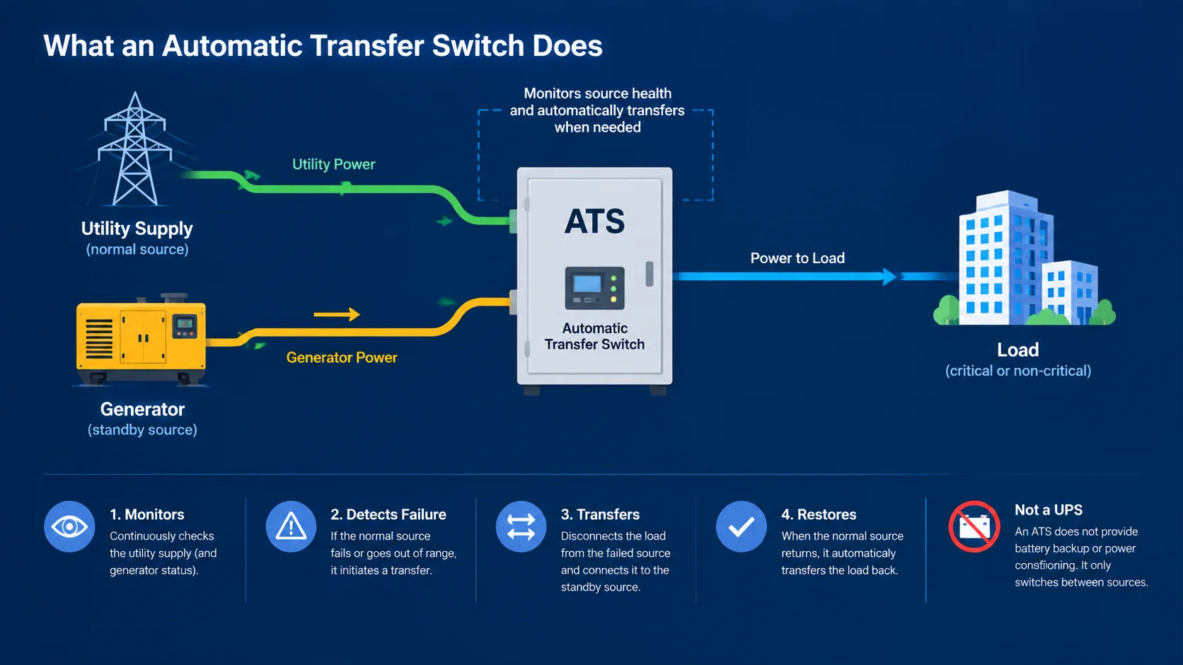
An automatic transfer switch (ATS) has one job: detect that the normal supply has failed, start the standby source if required, and move the load across fast enough that nothing important notices. In a data centre that window is measured in milliseconds. In a suburban home with a battery backup it is measured in seconds. Both are correct — for different equipment.
Choosing the right device means answering three questions: how critical is the load, how fast does the transfer need to be, and does the switch itself need to provide fault protection? This guide walks through PC class versus CB class, pole and current selection, transfer timing, and the installation details that decide whether the system works when the grid actually drops.
An ATS sits between two power sources — typically a utility supply and a generator, or a utility supply and a battery/inverter system — and a single outgoing load. It continuously monitors the normal source. When the voltage falls outside acceptable limits or fails entirely, the controller initiates a transfer sequence that opens the normal source contact and closes the standby source contact. When the normal supply returns and stabilises for a set period, it transfers back.
It is not a UPS. A UPS carries the load on stored energy and never breaks the supply; an ATS breaks and remakes the connection between two sources. The transfer time is therefore a real interruption, and how long it lasts is a specification decision, not an accident.
Under IEC 60947-6-1, automatic transfer switching equipment is divided into classes that differ in how much protection the switch itself provides. The practical choice is almost always between PC class and CB class.
| Feature | PC Class ATS | CB Class ATS |
|---|---|---|
| Switching function | Yes | Yes |
| Short-circuit protection | No — requires an upstream SCPD | Yes — independent breaking capacity |
| Overload protection | No | Yes — thermal or electronic trip unit |
| Switching mechanism | Solenoid or motor drive | Circuit breaker mechanism |
| Typical transfer speed | Fast, often under 50 ms | Slower, often seconds |
| Typical applications | Distribution boxes, PV and battery backup, non-critical loads | Main feeders, generators, critical loads |
| Relative cost | Lower | Higher |
| Size and complexity | Compact, simple | Larger, more complex |
A PC class ATS is a switching device only. It has no independent short-circuit breaking capacity and no overload protection, so it must always be paired with an upstream short-circuit protective device (SCPD) — a breaker or fuse that handles fault clearing.
That limitation is also its advantage. With no tripping mechanism in the current path, the device is mechanically simple, compact and fast. It is well suited to applications where the upstream protection already covers the circuit and where transfer speed or switching endurance matters more than integrated protection:
A CB class ATS is built on a circuit breaker frame and provides switching plus protection in one device. It has its own defined breaking capacity and is equipped with thermal-magnetic or electronic trip units tested under overload conditions. It can operate standalone without relying on an upstream device for fault clearing.
This is the choice for main feeders and critical loads:
CB class is not automatically better. It costs more and takes up more space, and for a small distribution board protecting a lighting circuit it is simply an expensive answer to a question nobody asked.
Transfer time is the interval between losing the normal source and restoring power from the standby source. It has two parts: the detection and decision delay set in the controller, and the physical switching time of the mechanism.
| Load type | Typical tolerance | Practical implication |
|---|---|---|
| Motors and pumps | Hundreds of milliseconds | Contactors may drop out; consider restart logic |
| IT and control equipment | Milliseconds | Requires fast PC class transfer, or a UPS in front of the ATS |
| Lighting | Seconds | Standard transfer timing is acceptable |
| HVAC and refrigeration | Seconds | Verify compressor restart delay after transfer |
| Life-safety systems | Code-defined | Follow local code and the fire safety specification |
Where the load genuinely cannot tolerate any interruption — server rooms being the classic case — the correct architecture is a UPS carrying the critical load, with the ATS protecting the UPS input rather than the servers directly. Expecting an ATS alone to hold up IT equipment is a common and expensive misunderstanding.
| Mistake | Consequence | Correct approach |
|---|---|---|
| PC class ATS without upstream SCPD | No fault clearing capability at all | Always specify and install the SCPD pairing |
| Sizing on running current only | Overload or nuisance tripping on motor starting | Account for inrush and future load growth |
| Forgetting neutral switching on 4-pole systems | Incorrect earthing, potential safety hazard | Match pole count to the system earthing arrangement |
| No transfer time delay on the return | Repeated cycling when the utility supply is unstable | Set a return delay long enough to ride through transient dips |
| Commissioning without simulated outage testing | Fault discovered during a real outage | Simulate source failure and verify both transfer directions |
| No airflow or access around the device | Overheating, difficult maintenance | Follow the manufacturer’s clearance requirements |
Automatic transfer switching equipment is covered by IEC 60947-6-1, which defines the classes and the test regime each must pass. PC class devices are subject to a conditional short-circuit test and must specify the compatible upstream SCPD models and ratings. CB class devices must prove breaking capacity independently through a full making and breaking test.
In North American markets, UL 1008 applies to transfer switch equipment. Because the test requirements and marking conventions differ between standards, a device cannot be assumed compliant with a specification simply because the switching function is similar. Confirm the certification relevant to the destination market.
No. A PC class ATS has no short-circuit breaking capacity of its own, so it must always be installed with a compatible upstream short-circuit protective device. The required SCPD type and rating are specified by the ATS manufacturer.
Not necessarily. CB class provides integrated protection but costs more and is physically larger. For terminal distribution circuits and non-critical loads where upstream protection already exists, PC class is often the more practical and economical choice.
Transfer time is how long the load is interrupted when the normal supply fails. Return time is the delay before switching back once the normal supply is restored — it exists to avoid repeated cycling during unstable utility conditions.
It depends on the system. A single-phase load needs 2 poles. Three-phase systems without neutral switching use 3 poles, while systems requiring the neutral to be switched use 4 poles. The correct answer follows the earthing arrangement and local wiring rules.
Most ATS controllers provide a generator start signal as a standard feature. The ATS monitors the utility supply and, on failure, sends a start command; it transfers once the generator output is within acceptable voltage and frequency limits.
Generally no. Transfer involves a real interruption, and even the fastest PC class device will drop most IT equipment. Server rooms normally use a UPS on the critical load, with the ATS managing the supply to the UPS or the mechanical infrastructure.
The class decision, the current rating, the pole count and the transfer time requirement are the four points that determine whether an ATS installation performs as intended. Work through them in that order and most of the specification falls into place before you look at a catalogue.
You can compare available options in the automatic transfer switch range, which covers PC class and CB class devices across a wide current span. For generator changeover, the RMQ1 series 100 A to 630 A 4-pole ATS is built for main switchboard duty, while the MLQ5 PC class dual power switch suits compact distribution and backup applications.
Not sure which class fits your fault level and load profile? Tell us the system voltage, load current and whether upstream protection already exists, and we will confirm the right configuration.