Types of Surge Protective Devices
Compare Type 1, Type 2 and Type 3 surge protective devices, AC vs DC SPDs, and the ratings that decide the right choice for your installation.
Read More

A miniature circuit breaker (MCB) is a small device with a short specification, and most selection mistakes come from reading only part of it. The amp rating gets all the attention, but the trip curve, breaking capacity and pole configuration are what determine whether the breaker protects the cable properly, avoids nuisance tripping, and can actually clear a fault at the end of the run.
This guide covers B, C and D curves, how to match breaking capacity to prospective fault current, when a 1P device is enough and when you need 2P, 3P or 4P, and how an MCB differs from an RCBO, RCCB and MCCB. It is written for installers, panel builders and buyers specifying final circuits and distribution boards.
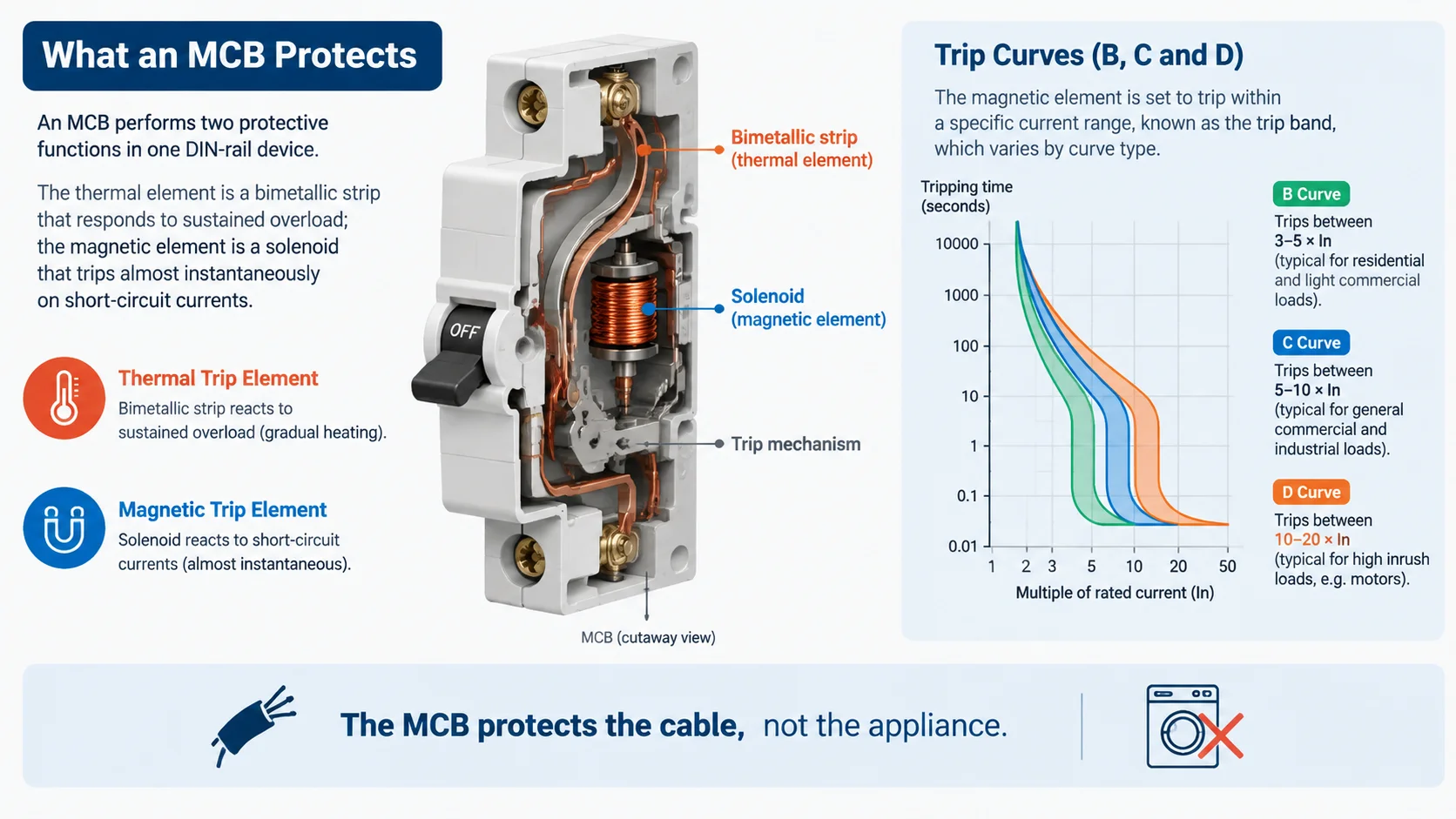
An MCB performs two protective functions in one DIN-rail device. The thermal element is a bimetallic strip that responds to sustained overload, tripping inversely with time — a slight overload takes minutes, a large one takes seconds. The magnetic element is a solenoid that trips almost instantaneously on the very high currents produced by a short circuit.
The device protects the cable, not the appliance. That distinction matters, because it sets the sizing rule: the breaker’s rated current must be high enough to carry the normal load without tripping, and low enough to protect the conductor it feeds.
Before choosing a curve or a pole count, three current values need to be established. They are normally expressed as a simple relationship.
The relationship is Ib ≤ In ≤ Iz. In practice the step that gets skipped is the middle one: Iz must be the derated value, not the base figure from a cable table. A cable rated 20 A in free air may only be good for 14 A when run inside a warm, crowded enclosure with other loaded circuits. Choosing a 16 A MCB because the load is 16 A, without checking the derated cable capacity, is one of the most common ways to end up with an unprotected cable.
The trip curve defines the multiple of the rated current at which the magnetic element operates instantaneously. It is the single most important parameter for avoiding nuisance tripping without sacrificing fault protection.
| Trip curve | Magnetic trip range | Typical application |
|---|---|---|
| Type B | 3–5 × In | Purely resistive loads, long cable runs, sensitive IT circuits |
| Type C | 5–10 × In | General lighting, standard socket circuits, mixed loads with moderate inrush |
| Type D | 10–20 × In | Motors, transformers, welders, large LED driver banks, high-inrush loads |
| Type K | 8–12 × In | Specialised motor control circuits under IEC 60947-2 |
| Type Z | 2–3 × In | Electronic and semiconductor loads needing maximum sensitivity |
Type C is the usual starting point for commercial and light-industrial final circuits because it tolerates the moderate inrush of LED drivers, small motors and switch-mode power supplies. But it is a starting point, not a default — the cable protection, earth-fault loop impedance and the actual load profile still govern the final choice.
Real inrush behaviour is what the curve is matched against. These figures are field-oriented starting points, not design values — confirm with the equipment nameplate or measured data.
| Load type | Typical inrush multiplier | Starting curve |
|---|---|---|
| Incandescent lighting, resistive heaters | 1.0–1.1 × | B |
| Small switch-mode supplies, routers, chargers | 1.2–2.5 × | B or C |
| LED drivers, domestic fixtures | 3–8 × | C |
| Refrigeration and heat pump compressors | 6–12 × | C, moving to D if nuisance trips persist |
| Transformers, magnetising inrush | 8–20 × | D |
| Welders and inverters | 10–20 × | D |
Aggregated inrush deserves particular attention. Ten LED fixtures switching on together do not behave like one fixture switching on ten times. Where a circuit feeds a bank of drivers or a row of SMPS units, the combined inrush can push a Type B device over its magnetic threshold at switch-on even though steady-state current is modest.
Breaking capacity is the maximum fault current an MCB can safely interrupt without damage or failure. It is expressed in kiloamperes, with common values of 6 kA, 10 kA and 15 kA.
The rule is simple and non-negotiable: the device’s breaking capacity must be equal to or greater than the prospective short-circuit current available at its installation point. A 6 kA device installed where the available fault current is 9 kA will not clear the fault safely.
| Standard | Rating used | Typical application |
|---|---|---|
| IEC 60898-1 | Icn — rated short-circuit capacity | Household and similar installations |
| IEC 60947-2 | Icu / Ics — ultimate and service breaking capacity | Industrial installations and distribution boards |
Note the standard as well as the number. A domestic device certified to IEC 60898-1 is not automatically acceptable where the specification calls for an industrial IEC 60947-2 device, even if both carry the same current and curve marking.
Where the available fault current exceeds the MCB’s capacity, the practical options are to select a higher-capacity device or to rely on verified backup protection from an upstream current-limiting device. Backup protection must be confirmed against the manufacturer’s coordination tables for the exact device pair — it cannot be assumed.
The pole count determines how many live conductors the device switches and protects, and it follows the system arrangement rather than personal preference.
| Configuration | Conductors protected | Typical use |
|---|---|---|
| 1P | Single phase conductor | Residential final circuits in TN systems with a solidly earthed neutral |
| 1P+N | Phase plus switched neutral, overcurrent on phase only | Final circuits where the neutral must be isolated with the phase |
| 2P | Two conductors, overcurrent protection on both | Single-phase circuits requiring full isolation, some TT applications |
| 3P | Three phase conductors | Three-phase motor and distribution circuits |
| 4P | Three phases plus neutral | Three-phase circuits where the neutral is switched and protected |
The distinction between 1P+N and 2P is worth understanding, because it is frequently confused. A 1P+N device switches and isolates the neutral but provides overcurrent protection only on the phase conductor. A true 2P device protects both poles. Which one is correct depends on the earthing system and the isolation requirement.
These four devices are often referred to loosely as “breakers,” but they provide different protection and are not interchangeable.
| Device | Overload & short circuit | Earth leakage | Typical position |
|---|---|---|---|
| MCB | Yes | No | Final circuits and sub-distribution |
| RCCB | No | Yes | Upstream of MCBs, protecting a group of circuits |
| RCBO | Yes | Yes | Individual final circuits needing both protections |
| MCCB | Yes | No | Main and sub-main distribution at higher currents |
A common arrangement is an RCCB protecting a group of MCB-fed circuits, which is economical but means a single earth fault takes out the whole group. An RCBO combines both functions per circuit, so a fault trips only the affected circuit — at higher cost per way, but with far better selectivity. Where continuity matters, RCBOs pay for themselves in avoided callouts.
MCCBs take over above the practical current limit of an MCB, typically from around 125 A upwards, and are used for main incomers and sub-mains where adjustable trip settings and higher breaking capacity are needed.
| Mistake | Consequence | Correct approach |
|---|---|---|
| Stepping up to a D curve to stop nuisance tripping | The higher magnetic threshold may fail to clear a worst-case fault | Fix the curve for the load, then re-verify the minimum fault current will still trip it |
| Sizing from base cable tables | Derated cable capacity is exceeded in service | Apply ambient, grouping and enclosure derating factors before choosing In |
| Assuming all B, C or D devices are equal | Different breaking capacity, accessories or certification than required | Confirm the full part number, standard and certification |
| Using a domestic device on an industrial specification | Non-compliance with the project standard | Match IEC 60898-1 or IEC 60947-2 to the specification |
| Ignoring aggregated inrush on LED banks | Repeated switch-on tripping on a correctly sized circuit | Consider the combined inrush of all drivers on the circuit |
Type C is a common starting point for commercial and light-industrial circuits because it tolerates moderate inrush. It is not automatically correct — cable protection, loop impedance and the actual load profile still govern the final decision.
Only after verifying fault-current and disconnection-time requirements. The current rating stays at 16 A, but a D curve needs substantially more instantaneous current to trip magnetically, which can mean the device no longer operates within the required time on a fault at the end of a long cable run.
An MCB provides overload and short-circuit protection only. An RCBO provides those plus residual current (earth leakage) protection in the same device. An RCBO is used where a single circuit needs earth leakage protection without affecting the rest of the board.
Estimate the prospective short-circuit current at the point of installation — from utility data, transformer rating and cable impedance, or by measurement — then select a device with a breaking capacity equal to or greater than that value, with margin.
No. A 1P+N device switches and isolates the neutral but provides overcurrent protection on the phase conductor only. A 2P device provides overcurrent protection on both poles. The correct choice depends on the earthing system and isolation requirements.
Icn is the rated short-circuit capacity defined under IEC 60898-1 for household and similar devices. Icu is the ultimate breaking capacity under IEC 60947-2 for industrial devices, with Ics defining the service breaking capacity the device can withstand repeatedly. They come from different standards and are not directly comparable.
Selecting an MCB is a short, ordered process: establish the load current, confirm the derated cable capacity, match the curve to the inrush, verify the breaking capacity against the available fault current, then settle the poles and accessories. Skipping any of those steps usually shows up later as either a tripping complaint or an unprotected cable.
You can review the MCB range for standard final-circuit devices, or the DZ47-125 high-breaking MCB series where a higher breaking capacity is needed. For circuits that also require earth leakage protection, the COB1LE-63 RCBO series combines both functions, and the COB1-63 DC series covers DC-side circuits in solar and battery applications.
Working on a board upgrade and need to confirm curves, ratings and pole configurations against your fault level? Send us the system details and we will check the specification against the available range.